■Description
■Agency approvals/Compliance
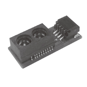
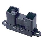
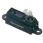
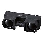
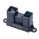
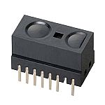
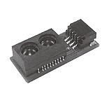
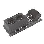
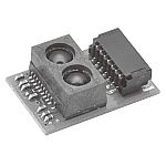
GP2Y0E02A is a distance measuring
sensor unit, composed of an
integrated combination of CMOS image
sensor and IR-LED.
The variety of the reflectivity of
the object, the environmental
temperature and the operating
duration are not influenced easily
to the distance detection because of
adopting the triangulation method.
This device outputs the voltage
corresponding to the detection
distance. So this sensor can also be
used as a proximity sensor.
■Features
1. Infrared LED and CMOS image
sensor with built-in signal
processing circuit
2. Distance measuring range : 4 to
50 cm
3. Low voltage operation : Min 2.7V
4. Compact size (18.9 × 8.0 × 5.2mm)
5. High-precision measurement
6. Analog output type
1. Compliant with RoHS directive
(2002/95/EC)
■Applications
1. Cleaning Robot
2. Human type Robot
3. Touch-less switch
(Sanitary equipment, Control of
illumination, etc)
4. Sensor for energy saving
(ATM, Copier, LCD monitor, etc)
5. Amusement equipment
(Robot, game machine, etc)
■Schematic

Please use an electric source
with an output current of 150mA or
more because LED pulse current is
more than 100mA.
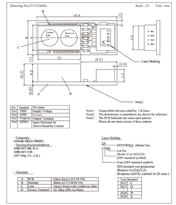
■Outline
■Absolute maximum ratings

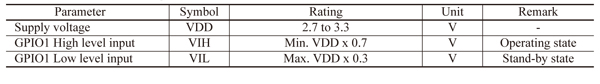
■Recommended operating conditions
■Electro-optical Characteristics
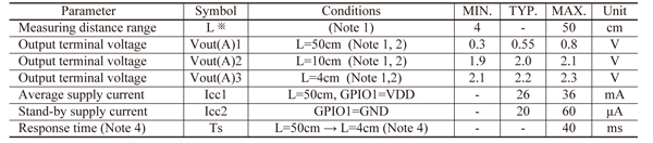
※ L : Distance to reflective object
(Note 1) Under dark condition
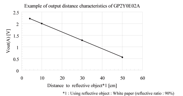
(Note 2) Using reflective object :
White paper (Made by Japan Color
Research Institute order made color
chart : mat, reflective ratio : 90%)
(Note 3) Max. time means that it
takes time to stabilize output due
to the change of reflected signal
light.
Definition : the case that object
condition is changed suddenly from
the least reflection(max. gain
condition in internal circuit) to
the most reflection (min. gain
condition in internal circuit).
(Note 4) Method of measuring (Ts)
Connect GPIO1 with GND during
measuring L=50cm with reflective
object: Gray paper (mat, reflective
ratio : 10%).
After changing the position (L=4cm
with reflective object: White paper
(mat, reflective ratio : 90%),
Measuring the time of the output
terminal : Vout(A) until stabilizing
.
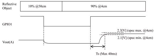
■Timing Chart
Active / Stand-by timing sequence
GPIO1 is set High or Low to control
Active/stand-by state. GPIO1=high :
Active state
GPIO1=Low : Stand-by state
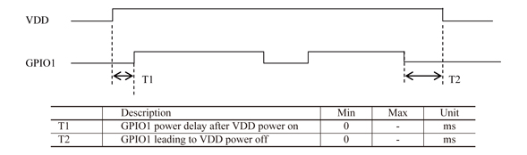
GPIO1 should be set after or at the
same time VDD has turned on. In case
that VDD turn off, GPIO1 should be
pull low.
If this product is operated under
the condition except the above, this
product or other device around it
may give damage due to excessive
current.
■Supplements
1. Example of output distance
characteristics
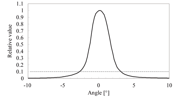
2. Example of directional angle of
emitting beam
■Notes
[Advice for the optics]
●Lens of this device shall be kept
cleanly. There are cases that dust,
water or oil and so on deteriorate
the characteristics of this device.
Please consider in actual
application.
●In case that protection cover is
set in front of this sensor , the
protection cover shall be
recommended to use material
which doesn’t scatter light and be
matt finish. And the protection
cover which has the most efficient
transmittance
at the emitting wavelength range of
LED for this product (λ=850nm±70nm).
And this protection cover is
recommend to be flat. And this
protection cover shall be
recommended to be parallel to the
emitter and detector portion. In
case that protection cover is set in
front of this sensor, It emits
reflected light from this protection
cover. If this reflect light reaches
in detector portion, the output
distance of this product may be
changed. The output distance
characteristics of this product may
be changed with according to
material (①) or transmittance (②) or
the thickness (③) or the distance
between the protection cover and
this product (④) or the angle
between surface and back (⑤) or the
angle between this cover and this
sensor(⑥). In case that protection
cover is set, please design to
consider that this reflective light
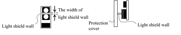
is minimized. And it shall be
effective to put light shield wall
between emitting lens and receiving
lens as shown in below.
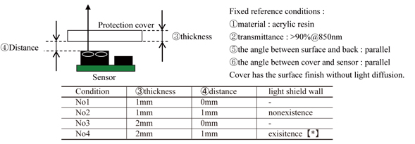
Direct reflective light becomes
large as Distance from sensor to
protection cover and thickness of
this cover become large. In case
thickness is 2mm and distance is
1mm, measuring distance is changed
shift larger from actual distance
than other condition. It shifts can
make small by using installation of
light shield【*】and compensation
function【**】.
【*】Noted for installation of light
shield
Inner distance between lens of
detector and lens of emitter is
around 0.6mm (reference). So the
width of light shield is recommended
to be less than 0.6mm. In case the
width of light shield is longer than
inner distance, measuring distance
is changed by Shield a part of
emitter lens or detector lens.
Please confirm that there is no
problem under the actual equipment.
And In case between protection cover
and light shield or between light
shield and this sensor exists space,
The effect of light shield is small
because light from emitter leaks.
The light shield wall is recommended
to use the material that have the
low transmittance at the emitting
wavelength range of LED for this
product (λ=850nm±70nm).
When the material of light shield
wall is hard, and the power stress
in which it is added to this product
is large, measuring distance may
shift from actual distance.
【**】Noted of compensation
function
The width of light shield wall
Protection Light shield wall
cover
This product has the function which
rectifies error shift by the direct
reflective light from protection
cover. The accuracy after
compensation is based on a
protection cover or its installation
condition. This function can be
active when it set correction factor
in this product by E-fuse. Please
refer to application manual about
the detail of this function.
Neither installation of a light
shield wall nor use of a
compensation function guarantees the
distance characteristic. These
improve error shift of the distance
characteristic.
Regardless of use of a light
shield wall or a compensation
function, please use it after
confirming with customer’s product.
【**】Noted of compensation function
The width of light shield wall
Protection Light shield wall
cover
This product has the function which
rectifies error shift by the direct
reflective light from protection
cover. The accuracy after
compensation is based on a
protection cover or its installation
condition. This function can be
active when it set correction factor
in this product by E-fuse. Please
refer to application manual about
the detail of this function.
Neither installation of a light
shield wall nor use of a
compensation function guarantees the
distance characteristic. These
improve error shift of the distance
characteristic.
Regardless of use of a light
shield wall or a compensation
function, please use it after
confirming with customer’s product.
[Advice for the characteristics]
●In case that there is an object
near to light exits of the sensor
between the sensor and the detected
object, please use this device after
confirming sufficiently what the
characteristics of this sensor do
not change by the object.
●This product has the function to
remove disturbance light by the
cancellation function of ambient
light, a visible light cut
lens, etc. But when the detector
receive direct light from the sun,
tungsten lamp and so on, there are
cases that it can not measure the
distance exactly. Please consider
the design that the detector does
not receive direct light from such
light source. When you operate the
customer’s set installing this
product by the remote control,
please consider soft that the output
of this product being disregarded at
the time of remote control operation
by software.
●Distance between sensor and mirror
reflector cannot be measured
exactly.
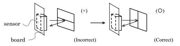
●In case that reflective object has
boundary line clearly, there is
cases that distance can not measure
exactly.
At that time, if direction of
boundary line and the line between
emitter center and detector center
are parallels, it is possible to
decrease deviation of measuring
distance.
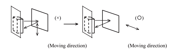
●In order to decrease measuring
error due to moving direction of
object, we recommend to mount the
sensor like below drawing.
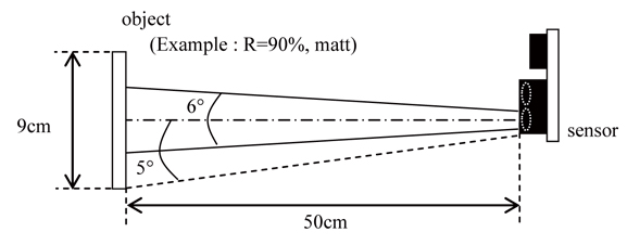
●For satisfying the specification of
the electro optical characteristic,
it is necessary to install a flat
surface of object in vertical of
emitted light, and it is necessary
to reflect the whole emitted light
as shown in the following figure. As
shown in the example of directional
angle of emitting beam, The angle is
around 6 ° (±3°) where emission
becomes 10% of peaks. The object
needs to exist in whole around 10
degrees (±5 degrees) area including
the variation of peak position. For
example, when the object is in 50
cm, it is necessary to install the
object of at least 9cm diameter
parallel to the surface of this
sensor as follows. However above
example doesn’t guarantee
specification, please use it after
confirming with customer’s product.
[Notes on handling]
50cm
●Please don’t do washing. Washing
may deteriorate the characteristics
of optical system and so on.
Please confirm resistance to
chemicals under the actual usage
since this product has not been
designed against washing.
●Please use this product under the
condition that applied stress to the
connector below 0.49N. And, harness
is pulled
in the state where it attached this
sensor, or please be careful so that
the stress more than the above may
not be added to this sensor.
●This product have the parts that
mount to the substrate by soldering
. Since there is a possibility that
a solder mounting
part may break when this product is
used, the stress more than 4.9N
should not be added to this product.
■Compliance with each regulation
1. The RoHS directive(2002/95/EC)
This product complies with the RoHS
directive(2002/95/EC) .
Object substances: mercury, lead
(except for lead in high melting
temperature type solders and glass
of electronic components), cadmium,
hexavalent chromium, polybrominated
biphenyls (PBB) and polybrominated
diphenyl ethers (PBDE)
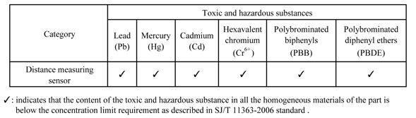
2. Content of six substances
specified in Management Methods for
Control of Pollution Caused by
Electronic Information
Products Regulation (Chinese :
电子信息产品污染控制管理办法).
■Packing specification
(Drawing No. CY15127i09)
.jpg)
(1) Packing number
Max 100 pieces per tray
Max 1000 pieces per case
(2) Close the lid of case and seals
with craft tape, and fill in the
blanks of Model No., quantity and
date. (3) Outside : 286 x 173 x 105
(mm)
(4) Indication
The content of the indication
conforms to EIAJ C-3 and the
following items are indicated.
Model No., Internal production
control name, Quantity, Packing
date, Corporate name, Country of
origin
■Important Notices
The circuit application examples
in this publication are provided to
explain representative applications
of SHARP devices and are not
intended to guarantee any circuit
design or license any intellectual
property rights. SHARP takes no
responsibility for any problems
related to any intellectual property
right of a third party resulting
from the use of SHARP's devices.
Contact SHARP in order to obtain
the latest device speci- fication
sheets before using any SHARP
device. SHARP re se r v e s t he ri
g ht to mak e changes in the
specifica - tions, characteristics,
data, materials, structure, and
other contents described herein
at any time without notice in
order to improve design or
reliability. Manu-
facturing locations are also subject
to change without notice.
Observe the following points
when using any devices in this
publication. SHARP takes no
responsibility for damage caused by
improper use of the devices which
does not meet the conditions and
absolute maximum ratings to be used
specified in the relevant
specification sheet nor meet the
following conditions:
(i) The devices in this publication
are designed for use in general
electronic equipment designs such
as:
--- Personal computers
--- Office automation equipment
--- Telecommunication equipment
[terminal]
--- Test and measurement equipment
--- Industrial control
--- Audio visual equipment
--- Consumer electronics
(ii) Measures such as fail-safe
function and redundant design should
be taken to ensure reliability and
safety when SHARP devices are used
for or in connection
with equipment that requires higher
reliability such as:
--- Transportation control and
safety equipment (i.e., aircraft,
trains, automobiles, etc.)
--- Traffic signals
--- Gas leakage sensor breakers
--- Alarm equipment
--- Various safety devices, etc.
(iii) SHARP devices shall not be
used for or in connection with
equipment that requires an extremely
high level of reliability and safety
such as:
--- Space applications
--- Telecommunication equipment
[trunk lines]
--- Nuclear power control equipment
--- Medical and other life support
equipment (e.g., scuba).
If the SHARP devices listed in
this publication fall within the
scope of strategic products
described in the Foreign Exchange
and Foreign Trade Law of Japan, it
is necessary to obtain approval to
export such SHARP devices.
This publication is the
proprietary product of SHARP and is
copyrighted, with all rights
reserved. Under the copyright laws,
no part of this publication may be
reproduced or transmitted in any
form or by any means, electronic or
mechanical, for any purpose, in
whole or in part, without the
express written permission of SHARP.
Express written permission is also
required before any use of this
publication may be made by a third
party.
Contact and consult with a SHARP
representative if there are any
questions about the contents of this
publication